Introduction to RF Design Using EM Simulators
2016-10-31 by:CAE仿真在线 来源:互联网
1. Electricity with Good Manners
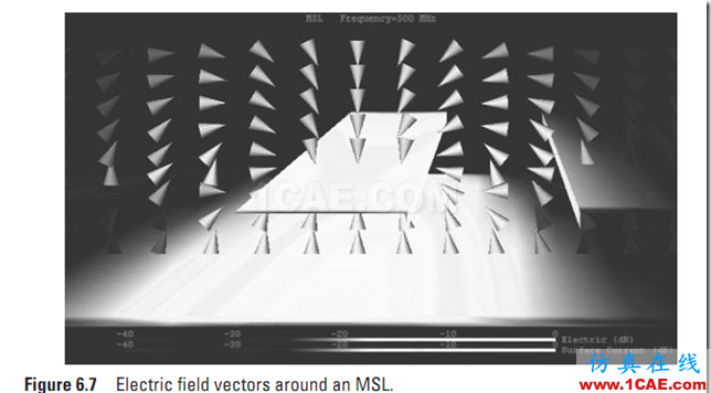
1. Electric and magnetic fi elds are widely distributed in the space around two parallel wires.
2. Electromagnetic wave energy is transmitted as the energy of the electric and magnetic field around the transmission lines.
3. When our transmission line is a waveguide tube, the electric and magnetic fi elds travel inside the tube, and radiation to the outside is minimized.
4. The microstrip line can be used to wire PCBs and multilayer substrateswhen high-frequency or high-speed operation is required.
5. The waves traveling on a transmission line can be viewed as a sum ofmodes. In typical application there is only one mode propagating on a transmission line.
6. Transmission lines are in wide use.
2. Electricity with Bad Manners
1. Electromagnetic energy tends to be radiated into free space from right angle bends and other discontinuities.
2. In general, the higher the frequency, the greater the displacement current and the higher the radiation.
3. At frequencies where the refl ection coeffi cient is large, standing waves will be generated.
4. Common mode currents can induce radiation.
3. What Happens at High Frequency
1. The engineer needs quantitative, accurate, numerical values in order to make decisions.
2. Delay is calculated from the phase angle of the S-parameters.
3. If there is a requirement on the allowed delay, it might be necessary to change the length of a line for the correct phase angle of the S-parameter.
4. By examining the magnitude of an S-parameter, we can determine if it exceeds the crosstalk value that can be allowed. If it does, it is necessary to modify the design, perhaps by separating the offending lines.
5. The characteristic impedance of a transmission line is important for efficiently transmitting electromagnetic energy to the load.
4. What Is Different About High-Frequency Circuits
1. Some electromagnetic field simulators have a feature to generate the SPICE subcircuit automatically.
2. Even in a circuit with more than 100 ports, SPICE models can be generated, including all couplings, with the help of electromagnetic field simulators.
3. The analysis time and required memory of large circuits can be significantly reduced by dividing the circuit into sections.
4. Electromagnetic field simulators can include lumped elements in acircuit.
5. Meta-materials (artificial media) can be created by aligning orderly structures periodically.
5. High Frequencies and Undesired Radiation
1. Return current flows on the ground plane of an MSL. The return current distribution looks almost like a mirror image of the line current.
2. Electromagnetic energy can be radiated into space where the return current encounters the slit. This radiation is typically undesired.
3. The magnitude of the undesired radiation caused by the slit in the ground is strongly dependent on the position and orientation of the slit and on the frequency.
4. If there is a slit in the ground, energy will be exactly split between the load, circuit losses, and radiation.
5. High-frequency electromagnetic shielding utilizes eddy currents to absorb and reflect incident radiation.
6. A wall with a surface resistance of 377 Ω absorbs (does not reflect) incident electromagnetic waves, provided the waves come from a suffi cient distance (i.e., they are plane waves).
6. Understanding the Differential Transmission Line
1. Properly designed shielded differential transmission line structures (e.g., stripline) are not prone to radiation and EMI because of the shielding effect of two grounds.
2. The crosstalk in a differential transmission line is smaller than in a similar microstrip line.
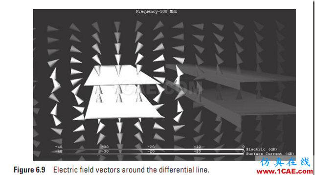
3. The differential transmission line tends to concentrate the electromagnetic field around the line, and thus less electromagnetic energy is coupled to other nearby lines than with similar microstrip line.
4. When positioning a differential transmission line on the edge of a substrate, the common mode component becomes a problem. This is not seen when the line is in the center of the substrate.
5. When positioning a differential transmission line on the edge of a substrate, a resonance occurs when ground plane is about an integer multiple of a half wavelength in size and transmission line common mode current couples to the ground plane. In this situation, electromagnetic waves are radiated.
7. Electromagnetic Compatibility Design Is Commonsense High-Frequency Design
1. The behavior of artificial systems in the electromagnetic environment is called electromagnetic compatibility.
2. A sealed metallic perfectly conducting housing (or case) has an infinite number of discrete resonant frequencies.
3. When there is a printed circuit in a sealed case, there is a possibility that the unwanted electromagnetic energy couples to the transmission lines and other components. This happens most strongly at resonant frequencies and can cause system failure.
4. Sometimes strong current fl ows along a joint with a resonant slit in the top cover. Secondary radiation can then couple to internal circuitry, and electromagnetic waves can leak outside.
5. Noise suppression sheets and radio wave absorbers can be simulated and used to reduce EMC problems.
8 All Roads Lead to Antennas
1. Maxwell predicted electromagnetic waves could travel in a completely empty, “transmission line named space,” and Hertz proved the existence of electromagnetic waves experimentally。
2. Electromagnetic field simulators are useful for the design of antennas.
3. Strong electric currents flow when an antenna resonates, and a standing wave is generated.
4. For antennas, “the object is to receive and transmit electromagnetic waves effi iently and accurately” and “an excellent receiving antenna is an excellent transmission antenna.”
5. For EMI, EMC, and EMS, circuits must be viewed as antennas, only now we wish to suppress the radiation, rather than enhance it.
6. “All roads lead to antennas!”
微带线

差分微带线

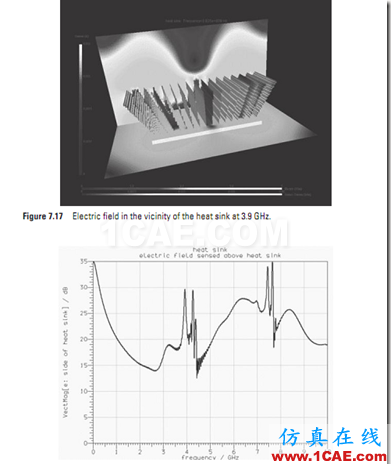
散热片的EMI问题

相关标签搜索:Introduction to RF Design Using EM Simulators HFSS电磁分析培训 HFSS培训课程 HFSS技术教程 HFSS无线电仿真 HFSS电磁场仿真 HFSS学习 HFSS视频教程 天线基础知识 HFSS代做 天线代做 Fluent、CFX流体分析 HFSS电磁分析


