
Workbench 框架建模中如何实现梁和板的截面偏置【转发】
2017-09-06 by:CAE仿真在线 来源:互联网
水哥很早之前出过采用ANSYS经典版本进行框架建模的相关文档和视频,其中关于梁和板的截面偏置问题进行了专题介绍(详见本公众号历史消息文章 《梁单元截面偏置(用户自定义位置)计算方法》)。但对于采用Workbench的同学来讲,该如何实现梁和板的截面偏置呢?今日水哥以一个简单的例子来说明在Workbench中如何实现上述问题。(注明:该例子无任何工程实际意义)
一个简单的框架结构,长宽高均为3.6m,采用Workbench对其进行建模,并实现截面偏置。
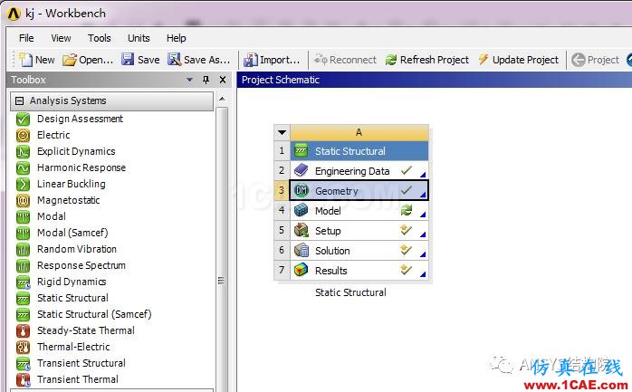
第一步,打开Workbench,新建静力分析,定义材料后,进入Dm进行物理建模。
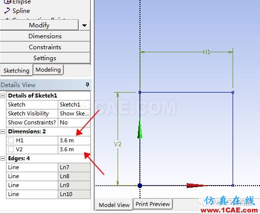
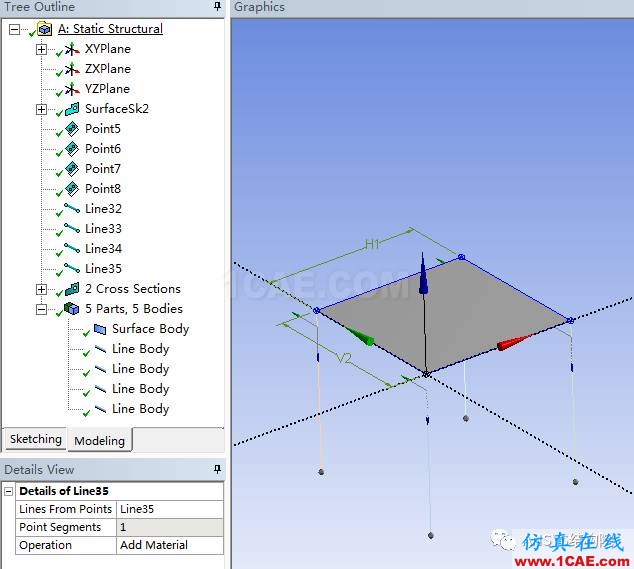
第二步,点击XY平面,进入草图绘制模式,绘制一矩形框,并定义尺寸为3.6mX3.6m.
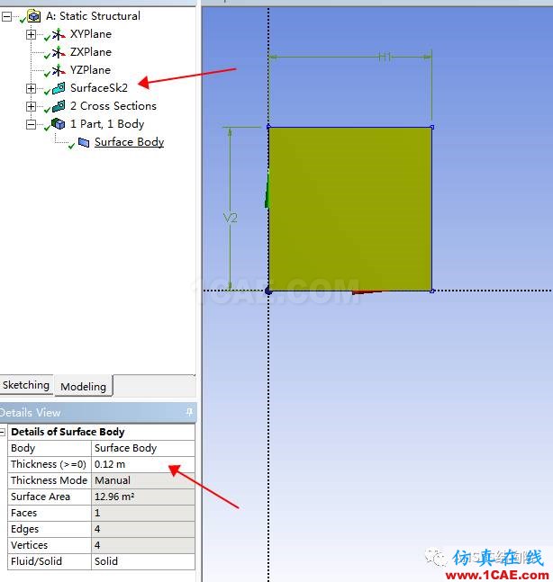
第三步,返回modeling,点击菜单栏中的Concept,点击 surface from sketches,生成我们的楼板物理模型,并在 body中定义楼板厚度为0.12m。
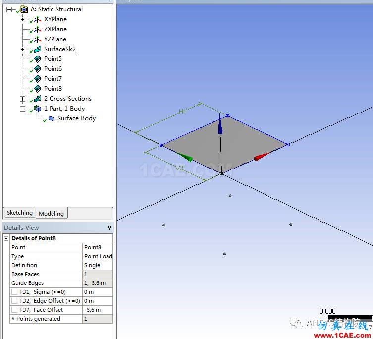
第四步,点击菜单栏中的Create,点击point, 一次生成下面四个关键点。
第五步,点击concept,点击line from points,依次生成四根柱子的物理模型。
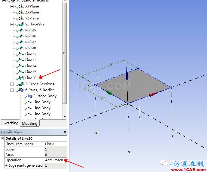
第六步,点击concept,点击line from edges,依次生成四根边梁的物理模型,注意在生成过程中 line的Operation 要选择add frozen.
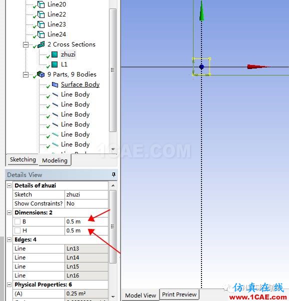
第七步,点击Concept--cross section--Rect,分别添加柱子和梁的截面,分别为0.5mX0.5m,0.25mX0.5m。
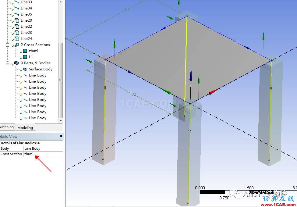
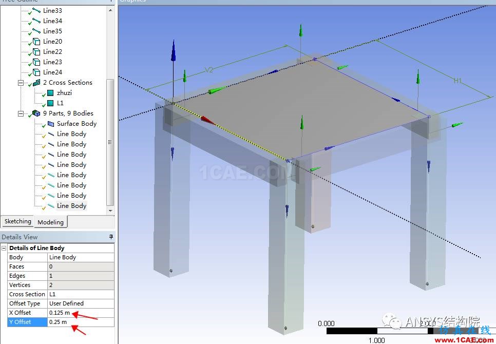
第八步,选择柱子body,选择截面类似为柱子,假定柱子不偏心,梁对其柱边缘。
选择梁线body,cross Section中选择L1截面,offset type 类型选择user defined,这时候就需要我们输入截面偏置距离,大小可以根据实时显示自己进行调试。
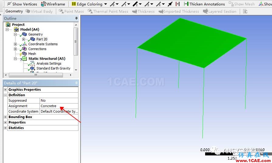
第九步,选择所有body,点击右键生成新的一个整体part,保存并关闭DM,进入model,更新几何数据,选中新的part,在assignment项目里选择材料类型进行赋值。
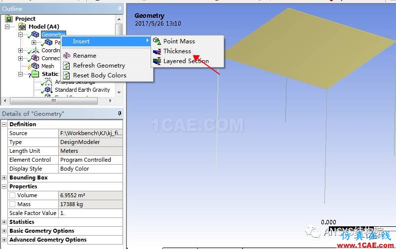
第十步,右键点击Geometry,点击insert,插入thickness。
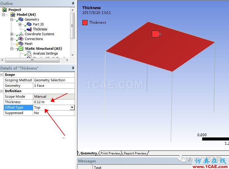
第十一步,选中楼板,输入厚度为0.12m,并指定offset type 为top.
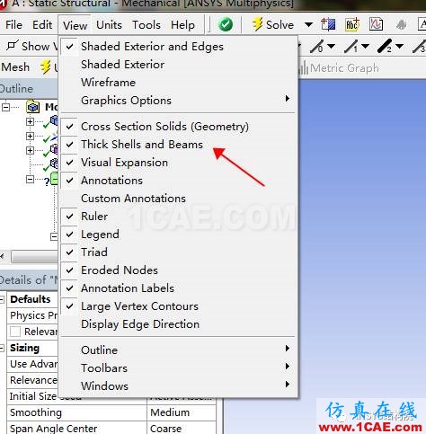
第十二步,保存模型,进入mesh,划分网格,点击View,打开thick shells and beams,即可看到我们的截面偏置效果。
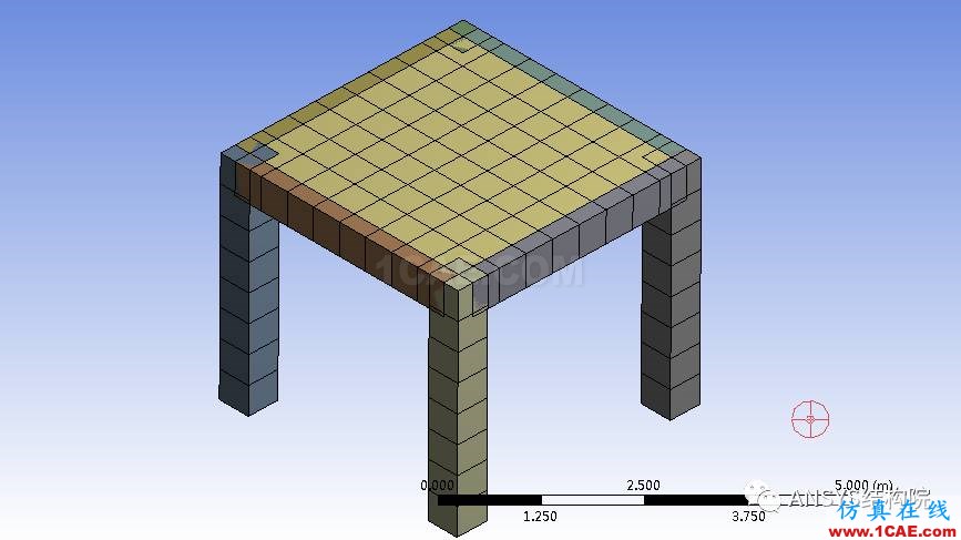
总结:从上述操作可见,采用Workbench进行截面偏置的操作方便性和效率要远远高于我们的经典版本,主要原因在于其在物理建模过程中我们就可以预览截面偏置效果,并且可以实时更换数据进行调整,而不用像类似经典版本那般,我们需要提前进行偏置距离的计算。
转自公众号:水哥 ANSYS结构院
相关标签搜索:Workbench 框架建模中如何实现梁和板的截面偏置【转发】 Ansys有限元培训 Ansys workbench培训 ansys视频教程 ansys workbench教程 ansys APDL经典教程 ansys资料下载 ansys技术咨询 ansys基础知识 ansys代做 Fluent、CFX流体分析 HFSS电磁分析 Abaqus培训


